How to see the output from the ARM LPC2103?

by Crossware 25. October 2011 10:36

A question we have just been asked is "How to see the output of the ARM LPC2103 on Crossware?".

We will assume that the user is interested in outputting messages from the excecuting ARM chip.

Here is a simple method of doing that.

Create a new project selecting the NXP LPC2103 as the target chip, accepting all defaults offered by the New Project Wizard.

Add:

printf("Hello world\n");

to main(). For example:

main()
{
    printf("Hello world\n");
    while (1)
    {
    }
}

Use the Headers Wizard to add the include file stdio.h to the xstdsys.h.  (Or manually add #include <stdio.h> to just above main().)

Build the project.

Run the program in the simulator and the Hello world message will appear in the Debug view.

Run the program on the hardware using the Jaguar USB debugger interface and the Hello world message will also appear in the Debug view.

How does this work?

The ARM7 debug communication channel (DCC) is being used to route the message to the Debug view.  A special putch() routine in the library sends the output to the DCC.  When you add printf() to your program, putch() is required as the output function.  If you do not include your own version of putch() in your program then this special library version will be automatically included.  When debugging with Jaguar, Jaguar captures the output from the DCC and the debugger writes it to the Debug view.  When simulating, the DCC is simulated and so the output is captured and written to the debug view in a similar way.

This use of the DCC is often referred to as 'semi-hosting'.  For more information on semi-hosting see the ARM Simulator and Debugger User Guide via the Books view or refer to this and following pages of the online version of the guide:

 http://www.crossware.com/smanuals/sdarm/semi_overview.html


Tags:

Blog

Fast variable bit-stream output in C on Cortex-M3

by Crossware 6. October 2011 13:36

In the previous post we described a method of outputting a fixed bit pattern to a port pin.  The method we used will work on all ARM chips - ARM7, ARM9 and Cortex-M3.  The result was a single write instruction for each output bit.

In this post we will use the bit-banding of the Cortex-M3 core to achieve a fast output of a variable bit stream.

The Cortex-M3 core has two bit-banded regions:

1. on-chip SRAM space starting at address 0X20000000 and

2. on-chip peripheral space starting at address 0X40000000.

To read or write a single bit in the on-chip SRAM space we write into the bit-banded region starting at 0X22000000.

To read or write a single bit in the on-chip peripheral space we write into the bit-banded region starting at 0X42000000.

The ARM documentation give the algorithm to calculate a bit address.  Using this information, we have defined four macros to simplify our coding:

#define byte_base_difference 0X20000000
#define byte_offset(a) (((unsigned long)&(a)) - byte_base_difference)
#define bit_word_offset(a, bit_number) ((byte_offset(a) * 32) + (bit_number * 4))
#define bit_word_addr(a, bit_number, bit_band_base) (bit_band_base + bit_word_offset(a, bit_number))

Now if we define a variable such as:

unsigned long nDWord;

the address of the first bit of this variable will be:

#define addrbit0 (unsigned long*)bit_word_addr(nDWord, 0, 0X22000000)

We can write a 32-bit value into nDWord using a normal assignment, and we can read it one bit at a time using the appropriate bit-band address.  Using this method we avoid the need to do any shifting.  (By the way, this method of avoiding shifts has been possible on the 8051 microcontroller for the last 30 years!)

Similarly we can use the same macros to define the address of a bit in an on-chip peripheral register.  For instance the address of bit 12 of the EFM32 port A data out register is:

#define addrDoutPA12 (unsigned long*)bit_word_addr(g_pGPIO->PA_DOUT, 12, 0X42000000)

We can use this address to write to this bit and set or clear pin PA12.  (Not forgetting to enable the GPIO clock and configure PA12 as an output using the GPIO graphical wizard.)

We can assign these addresses to locally defined pointers to ensure that the addresses are kept in registers:

unsigned long* pBit = addrbit0;
unsigned long* pPin = addrDoutPA12;

Then for instance to output bit 2 of nDWord to PA12, we can use a simple assignment:

*pPin = *(pBit + 2);

 Here is a function that will write all 32 bits of nDWord to PA12:

void output_pattern(unsigned long nPattern)
{
    nDWord = nPattern;         // get the bit-stream bits into bit-banded SRAM
    // local variables so that the reside in registers:
    unsigned long* pBit = addrbit0;
    unsigned long* pPin = addrDoutPA12;

    *pPin = *(pBit + 0);
    *pPin = *(pBit + 1);
    *pPin = *(pBit + 2);
    *pPin = *(pBit + 3);
    *pPin = *(pBit + 4);
    *pPin = *(pBit + 5);
    *pPin = *(pBit + 6);
    *pPin = *(pBit + 7);
    *pPin = *(pBit + 8);
    *pPin = *(pBit + 9);
    *pPin = *(pBit + 10);
    *pPin = *(pBit + 11);
    *pPin = *(pBit + 12);
    *pPin = *(pBit + 13);
    *pPin = *(pBit + 14);
    *pPin = *(pBit + 15);
    *pPin = *(pBit + 16);
    *pPin = *(pBit + 17);
    *pPin = *(pBit + 18);
    *pPin = *(pBit + 19);
    *pPin = *(pBit + 20);
    *pPin = *(pBit + 21);
    *pPin = *(pBit + 22);
    *pPin = *(pBit + 23);
    *pPin = *(pBit + 24);
    *pPin = *(pBit + 25);
    *pPin = *(pBit + 26);
    *pPin = *(pBit + 27);
    *pPin = *(pBit + 28);
    *pPin = *(pBit + 29);
    *pPin = *(pBit + 30);
    *pPin = *(pBit + 31);
}


The result is two instructions per line.  One to read the bit from SRAM and the next to write it to the port's data out register:

    LDR    R2,[R1]
    STR    R2,[R0]
    LDR    R2,[R1,#4]
    STR    R2,[R0]
    LDR    R2,[R1,#8]
    STR    R2,[R0]
    LDR    R2,[R1,#12]
    STR    R2,[R0]
    LDR    R2,[R1,#16]
    STR    R2,[R0]
    LDR    R2,[R1,#20]
    STR    R2,[R0]
    LDR    R2,[R1,#24]
    STR    R2,[R0]
    LDR    R2,[R1,#28]
    STR    R2,[R0]
    LDR    R2,[R1,#32]
    STR    R2,[R0]
    LDR    R2,[R1,#36]
    STR    R2,[R0]
    LDR    R2,[R1,#40]
    STR    R2,[R0]
    LDR    R2,[R1,#44]
    STR    R2,[R0]
    LDR    R2,[R1,#48]
    STR    R2,[R0]
    LDR    R2,[R1,#52]
    STR    R2,[R0]
    LDR    R2,[R1,#56]
    STR    R2,[R0]
    LDR    R2,[R1,#60]
    STR    R2,[R0]
    LDR    R2,[R1,#64]
    STR    R2,[R0]
    LDR    R2,[R1,#68]
    STR    R2,[R0]
    LDR    R2,[R1,#72]
    STR    R2,[R0]
    LDR    R2,[R1,#76]
    STR    R2,[R0]
    LDR    R2,[R1,#80]
    STR    R2,[R0]
    LDR    R2,[R1,#84]
    STR    R2,[R0]
    LDR    R2,[R1,#88]
    STR    R2,[R0]
    LDR    R2,[R1,#92]
    STR    R2,[R0]
    LDR    R2,[R1,#96]
    STR    R2,[R0]
    LDR    R2,[R1,#100]
    STR    R2,[R0]
    LDR    R2,[R1,#104]
    STR    R2,[R0]
    LDR    R2,[R1,#108]
    STR    R2,[R0]
    LDR    R2,[R1,#112]
    STR    R2,[R0]
    LDR    R2,[R1,#116]
    STR    R2,[R0]
    LDR    R2,[R1,#120]
    STR    R2,[R0]
    LDR    R2,[R1,#124]
    STR    R2,[R0]

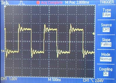
On an EFM32G890 chip running at 14MHz, outputting 0, 1, 0, 1, 0, 1 etc gave the following waveform:


Copyright © 2011 Crossware Products. All rights reserved.

Tags: , ,

Blog

Fast bit-stream output in C on ARM

by Crossware 5. October 2011 16:40

To output a bit-stream on an ARM chip, it is necessary to write to the registers of the GPIO peripheral.

On an Energy Micro EFM32 chip and many other ARM chips, there are separate GPIO peripheral registers to set and clear output pins.  This separation into SET and CLEAR registers enables one or more pins to be set or cleared with a single write operation.

However simply writing a constant into one of these registers will produce more than a single CPU write operation.  Due to the RISC nature of the ARM chip, the value of the constant and the address of the GPIO peripheral register must be in CPU registers.  So the compiler must generate code to:

1. load the constant into a CPU register,

2. load the address of the GPIO peripheral register into a CPU register and

3. perform the write operation

Depending on the address of the GPIO peripheral register, on a Cortex-M3 chip this may required 4 CPU instructions as follows:

g_pGPIO->PA_DOUTSET = 2;     // set PA1

    MOV    R0,#24592
    MOVT    R0,#16384
    MOV    R1,#2
    STR    R1,[R0]

Only the final STR instruction is setting the pin, the other three instructions are loading the CPU registers.

On an ARM7 or ARM9 chip, the address of the GPIO peripheral register may need to be stored in a memory pool requiring a data read from memory.  Even less efficient.

A bit-stream requires a sequence of writes.  To make sure that once loaded the CPU register stay loaded, the value of the constant and the address of the GPIO peripheral register can be pre-assigned to local variables.

By default the compiler will allocate the local variables to registers.

So if this is the C code:

 main()

{
    unsigned long nBit = 2;
    unsigned long* pSet = &g_pGPIO->PA_DOUTSET;
    unsigned long* pClear = &g_pGPIO->PA_DOUTCLR;
    while (1)
    {
        *pSet = nBit;       //set PA1
        *pClear = nBit;    // clear PA1
        *pSet = nBit;
        *pClear = nBit;
        *pSet = nBit;
        *pClear = nBit;
        *pSet = nBit;
        *pClear = nBit;
        *pSet = nBit;
        *pClear = nBit;
        *pSet = nBit;
        *pClear = nBit;
        *pSet = nBit;
        *pClear = nBit;
        *pSet = nBit;
        *pClear = nBit;
        *pSet = nBit;
        *pClear = nBit;
        *pSet = nBit;
        *pClear = nBit;
    }

}

The resulting CPU instructions generated by the compiler are:

    MOV    R2,#24592
    MOVT    R2,#16384
    MOV    R1,#2
    STR    R1,[R2]
    MOV    R0,#24596
    MOVT    R0,#16384
.@8
    STR    R1,[R0]
    STR    R1,[R2]
    STR    R1,[R0]
    STR    R1,[R2]
    STR    R1,[R0]
    STR    R1,[R2]
    STR    R1,[R0]
    STR    R1,[R2]
    STR    R1,[R0]
    STR    R1,[R2]
    STR    R1,[R0]
    STR    R1,[R2]
    STR    R1,[R0]
    STR    R1,[R2]
    STR    R1,[R0]
    STR    R1,[R2]
    STR    R1,[R0]
    STR    R1,[R2]
    STR    R1,[R0]
    B    .@8

The compiler has generated a continues uninterrupted seqeuence of writes.

This post shows how efficiently output a fixed bit-stream.  In the next post we will be looking at how to output a variable bit-stream.

Copyright © 2011 Crossware Products. All rights reserved.

Tags: , , , ,

Blog

About this blog

This is where you will find topical information that we think might be useful to you.

Month List