Fast variable bit-stream output in C on Cortex-M3

by Crossware 6. October 2011 13:36

In the previous post we described a method of outputting a fixed bit pattern to a port pin.  The method we used will work on all ARM chips - ARM7, ARM9 and Cortex-M3.  The result was a single write instruction for each output bit.

In this post we will use the bit-banding of the Cortex-M3 core to achieve a fast output of a variable bit stream.

The Cortex-M3 core has two bit-banded regions:

1. on-chip SRAM space starting at address 0X20000000 and

2. on-chip peripheral space starting at address 0X40000000.

To read or write a single bit in the on-chip SRAM space we write into the bit-banded region starting at 0X22000000.

To read or write a single bit in the on-chip peripheral space we write into the bit-banded region starting at 0X42000000.

The ARM documentation give the algorithm to calculate a bit address.  Using this information, we have defined four macros to simplify our coding:

#define byte_base_difference 0X20000000
#define byte_offset(a) (((unsigned long)&(a)) - byte_base_difference)
#define bit_word_offset(a, bit_number) ((byte_offset(a) * 32) + (bit_number * 4))
#define bit_word_addr(a, bit_number, bit_band_base) (bit_band_base + bit_word_offset(a, bit_number))

Now if we define a variable such as:

unsigned long nDWord;

the address of the first bit of this variable will be:

#define addrbit0 (unsigned long*)bit_word_addr(nDWord, 0, 0X22000000)

We can write a 32-bit value into nDWord using a normal assignment, and we can read it one bit at a time using the appropriate bit-band address.  Using this method we avoid the need to do any shifting.  (By the way, this method of avoiding shifts has been possible on the 8051 microcontroller for the last 30 years!)

Similarly we can use the same macros to define the address of a bit in an on-chip peripheral register.  For instance the address of bit 12 of the EFM32 port A data out register is:

#define addrDoutPA12 (unsigned long*)bit_word_addr(g_pGPIO->PA_DOUT, 12, 0X42000000)

We can use this address to write to this bit and set or clear pin PA12.  (Not forgetting to enable the GPIO clock and configure PA12 as an output using the GPIO graphical wizard.)

We can assign these addresses to locally defined pointers to ensure that the addresses are kept in registers:

unsigned long* pBit = addrbit0;
unsigned long* pPin = addrDoutPA12;

Then for instance to output bit 2 of nDWord to PA12, we can use a simple assignment:

*pPin = *(pBit + 2);

 Here is a function that will write all 32 bits of nDWord to PA12:

void output_pattern(unsigned long nPattern)
{
    nDWord = nPattern;         // get the bit-stream bits into bit-banded SRAM
    // local variables so that the reside in registers:
    unsigned long* pBit = addrbit0;
    unsigned long* pPin = addrDoutPA12;

    *pPin = *(pBit + 0);
    *pPin = *(pBit + 1);
    *pPin = *(pBit + 2);
    *pPin = *(pBit + 3);
    *pPin = *(pBit + 4);
    *pPin = *(pBit + 5);
    *pPin = *(pBit + 6);
    *pPin = *(pBit + 7);
    *pPin = *(pBit + 8);
    *pPin = *(pBit + 9);
    *pPin = *(pBit + 10);
    *pPin = *(pBit + 11);
    *pPin = *(pBit + 12);
    *pPin = *(pBit + 13);
    *pPin = *(pBit + 14);
    *pPin = *(pBit + 15);
    *pPin = *(pBit + 16);
    *pPin = *(pBit + 17);
    *pPin = *(pBit + 18);
    *pPin = *(pBit + 19);
    *pPin = *(pBit + 20);
    *pPin = *(pBit + 21);
    *pPin = *(pBit + 22);
    *pPin = *(pBit + 23);
    *pPin = *(pBit + 24);
    *pPin = *(pBit + 25);
    *pPin = *(pBit + 26);
    *pPin = *(pBit + 27);
    *pPin = *(pBit + 28);
    *pPin = *(pBit + 29);
    *pPin = *(pBit + 30);
    *pPin = *(pBit + 31);
}


The result is two instructions per line.  One to read the bit from SRAM and the next to write it to the port's data out register:

    LDR    R2,[R1]
    STR    R2,[R0]
    LDR    R2,[R1,#4]
    STR    R2,[R0]
    LDR    R2,[R1,#8]
    STR    R2,[R0]
    LDR    R2,[R1,#12]
    STR    R2,[R0]
    LDR    R2,[R1,#16]
    STR    R2,[R0]
    LDR    R2,[R1,#20]
    STR    R2,[R0]
    LDR    R2,[R1,#24]
    STR    R2,[R0]
    LDR    R2,[R1,#28]
    STR    R2,[R0]
    LDR    R2,[R1,#32]
    STR    R2,[R0]
    LDR    R2,[R1,#36]
    STR    R2,[R0]
    LDR    R2,[R1,#40]
    STR    R2,[R0]
    LDR    R2,[R1,#44]
    STR    R2,[R0]
    LDR    R2,[R1,#48]
    STR    R2,[R0]
    LDR    R2,[R1,#52]
    STR    R2,[R0]
    LDR    R2,[R1,#56]
    STR    R2,[R0]
    LDR    R2,[R1,#60]
    STR    R2,[R0]
    LDR    R2,[R1,#64]
    STR    R2,[R0]
    LDR    R2,[R1,#68]
    STR    R2,[R0]
    LDR    R2,[R1,#72]
    STR    R2,[R0]
    LDR    R2,[R1,#76]
    STR    R2,[R0]
    LDR    R2,[R1,#80]
    STR    R2,[R0]
    LDR    R2,[R1,#84]
    STR    R2,[R0]
    LDR    R2,[R1,#88]
    STR    R2,[R0]
    LDR    R2,[R1,#92]
    STR    R2,[R0]
    LDR    R2,[R1,#96]
    STR    R2,[R0]
    LDR    R2,[R1,#100]
    STR    R2,[R0]
    LDR    R2,[R1,#104]
    STR    R2,[R0]
    LDR    R2,[R1,#108]
    STR    R2,[R0]
    LDR    R2,[R1,#112]
    STR    R2,[R0]
    LDR    R2,[R1,#116]
    STR    R2,[R0]
    LDR    R2,[R1,#120]
    STR    R2,[R0]
    LDR    R2,[R1,#124]
    STR    R2,[R0]

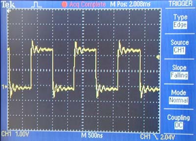
On an EFM32G890 chip running at 14MHz, outputting 0, 1, 0, 1, 0, 1 etc gave the following waveform:
 

Copyright © 2011 Crossware Products. All rights reserved.

Tags: , ,

Blog

Fast bit-stream output in C on ARM

by Crossware 5. October 2011 16:40

To output a bit-stream on an ARM chip, it is necessary to write to the registers of the GPIO peripheral.

On an Energy Micro EFM32 chip and many other ARM chips, there are separate GPIO peripheral registers to set and clear output pins.  This separation into SET and CLEAR registers enables one or more pins to be set or cleared with a single write operation.

However simply writing a constant into one of these registers will produce more than a single CPU write operation.  Due to the RISC nature of the ARM chip, the value of the constant and the address of the GPIO peripheral register must be in CPU registers.  So the compiler must generate code to:

1. load the constant into a CPU register,

2. load the address of the GPIO peripheral register into a CPU register and

3. perform the write operation

Depending on the address of the GPIO peripheral register, on a Cortex-M3 chip this may required 4 CPU instructions as follows:

g_pGPIO->PA_DOUTSET = 2;     // set PA1

    MOV    R0,#24592
    MOVT    R0,#16384
    MOV    R1,#2
    STR    R1,[R0]

Only the final STR instruction is setting the pin, the other three instructions are loading the CPU registers.

On an ARM7 or ARM9 chip, the address of the GPIO peripheral register may need to be stored in a memory pool requiring a data read from memory.  Even less efficient.

A bit-stream requires a sequence of writes.  To make sure that once loaded the CPU register stay loaded, the value of the constant and the address of the GPIO peripheral register can be pre-assigned to local variables.

By default the compiler will allocate the local variables to registers.

So if this is the C code:

 main()

{
    unsigned long nBit = 2;
    unsigned long* pSet = &g_pGPIO->PA_DOUTSET;
    unsigned long* pClear = &g_pGPIO->PA_DOUTCLR;
    while (1)
    {
        *pSet = nBit;       //set PA1
        *pClear = nBit;    // clear PA1
        *pSet = nBit;
        *pClear = nBit;
        *pSet = nBit;
        *pClear = nBit;
        *pSet = nBit;
        *pClear = nBit;
        *pSet = nBit;
        *pClear = nBit;
        *pSet = nBit;
        *pClear = nBit;
        *pSet = nBit;
        *pClear = nBit;
        *pSet = nBit;
        *pClear = nBit;
        *pSet = nBit;
        *pClear = nBit;
        *pSet = nBit;
        *pClear = nBit;
    }

}

The resulting CPU instructions generated by the compiler are:

    MOV    R2,#24592
    MOVT    R2,#16384
    MOV    R1,#2
    STR    R1,[R2]
    MOV    R0,#24596
    MOVT    R0,#16384
.@8
    STR    R1,[R0]
    STR    R1,[R2]
    STR    R1,[R0]
    STR    R1,[R2]
    STR    R1,[R0]
    STR    R1,[R2]
    STR    R1,[R0]
    STR    R1,[R2]
    STR    R1,[R0]
    STR    R1,[R2]
    STR    R1,[R0]
    STR    R1,[R2]
    STR    R1,[R0]
    STR    R1,[R2]
    STR    R1,[R0]
    STR    R1,[R2]
    STR    R1,[R0]
    STR    R1,[R2]
    STR    R1,[R0]
    B    .@8

The compiler has generated a continues uninterrupted seqeuence of writes.

This post shows how efficiently output a fixed bit-stream.  In the next post we will be looking at how to output a variable bit-stream.

Copyright © 2011 Crossware Products. All rights reserved.

Tags: , , , ,

Blog

Jaguar with slow running EFM32 microcontrollers

by Crossware 23. September 2011 21:14

If the Core clock of an Energy Micro EFM32 microcontroller is running slow, then it may be necessary for the operating frequency of Jaguar to be reduced.

To change the operating frequency of Jaguar, choose Project->Settings->Debug and select a Jaguar frequency divisor from the drop-down list.  Allowable divisors are 1, 2, 4, 8, 16 and 32.  The default when EFM32 firmware is installed is 1.

We experimented with the an EFM32G890 running from it's default 14MHz high speed internal RC clock and obtained the following results.

EFM Core Clock Divider     Required Jaguar Clock Divider
64 (220kHz)     32
32 (440kHz)     <=16
16 (880kHz)     <=8
8 (1.75MHz)     <=4
4 (3.5MHz)     <=2
2 (7MHz)     <=1
1 (14MHz)     <=1

If the EFM32 Core clock was divided by by 128, Jaguar was not able to run slow enough and so lost control.  In this situation, a mass erase may be required before Jaguar can take control again.

Keep in mind that the EFM32 high speed RC clock does not operate at a precise frequency and so our tests may not have been done at a base frequency of exactly 14MHz.

Tags: , , , ,

Blog

Atmel SAM3S Cortex-M3 based microcontrollers supported

by Crossware 5. September 2011 16:15

The Development Suite for ARM now includes comprehensive support for the Atmel SAM3S Cortex-M3 based microcontroller family.

The ARM Training System is available fitted with an Atmel SAM3S.


(If you require support for the SAM3N family, please let us know.)

Tags: , , ,

Blog

DAC simulation added for Energy Micro chips.

by Crossware 12. August 2011 13:12

Support for the Energy Micro chips now includes simulation of the DAC.

The outputs are sent to the Virtual Workshop Interface and so you can receive analog outputs in your own extensions.

The analog outputs are also sent to the appropriate ADC inputs.

The simulation DAC interacts with the simulating PRS and so the PRS can trigger a conversion and also generate a sine wave output.

Tags:

Blog

Uploaded new versions of ARM trial software

by Crossware 4. August 2011 13:11

New versions of ARM trial software have been uploaded.

The latest versions of the EFM32 extensions are included in the upload.

Tags:

Blog

ADC simulation added for Energy Micro chips

by Crossware 4. August 2011 13:10

We have added the ADC to the simulation of the EFM32Gxxx and EFM32TGxxx chips.

The ADC simulation links to the Virtual Workshop Interface and so you can input analog signals into the simulation chip.

The ADC receives triggers from the PRS and so you can program the timers to trigger the ADC and test your code using simulation.

Tags:

Blog

Support for Energy Micro Cortex-M3 based microcontrollers formally announced

by Crossware 29. July 2011 16:09

We have formally announced support for the Energy Micro Gecko and Tiny Gecko chips:

News release

The Energy Micro third party support page now includes a a link to our web site.

Tags: , , ,

Blog

Support added for EFM32TGxxx chips

by Crossware 28. July 2011 13:10

The Development Suite for ARM now supports the EFM32TGxxx Tiny Gecko chips from Energy Micro.  All of the features provided for the EFM32Gxxx Gecko chips are included for the EFM32TGxxx too.

Tags:

Blog

EFM32 simulation: GPIO, timers and PRS

by Crossware 25. July 2011 13:07

The GPIO, timers, peripheral reflex system (PRS) of the EFM32Gxxx chips are now simulated.

The I/O from the GPIO simulation will go though the Virtual Workshop Interface and so you can send and receive digital I/O to and from the simulation chip.

The timers interact with the PRS.

Simulation of the capture/compare features of the timers is not yet implemented.

Tags:

Blog

About this blog

This is where you will find topical information that we think might be useful to you.

Month List